Part 5 - Graphics (Basic)
Finally, we get on to a tutorial that moves us away from blinking an LED as we explore the VideoCore IV GPU's framebuffer.
Reference Material
We need some reading material for this tutorial - this is how I put the tutorial together, by reading and studying the manuals available for the Videcore, mainly for this tutorial the information comes from the BCM238x peripherals datasheet and the raspberrypi gpu mailbox documnetation.
Some material that's useful (Generally for late night reading!):
This information is less important for now, but worth noting:
Yes there's a lot of text and more than one manual - but that's the only way you learn!
The GPU (Videocore IV)
The GPU and ARM devices can communicate with each other through a mailbox system. However, don't forget that the ARM and GPU also share the memory space, and so although we have to communicate through the mailbox, this is what negotiates settings and a framebuffer. The framebuffer address in memory is then returned from the GPU and we can go ahead and write to the framebuffer to see graphics.
A framebuffer is a term that really refers to a block of video memory. This video memory is used to display pixels on the screen. So we have access to each pixel on the screen and can change it's colour properties. The framebuffer should be at least as big as the screen resolution. The size of the framebuffer memory block is given by a simple equation:
NOTE In this tutorial we'll be using a framebuffer and so won't have any higher-level functions like OpenGL or accelerated graphics. We're going to create a simple software renderer.
The number of bytes per pixel sets the number of colours available. The Raspberry-Pi GPU supports 8-bit, but in this mode the 8-bit value corresponds to a palette entry, and the palette appears to be very limited. A palette mode can be really useful as it's fast (minimal amount of memory required for the graphics) and can be really useful for some special effects by simply altering the palette. These were great techniques for fast graphics on the old 16-bit machines in the 1990s.
16-bit requires two bytes of data per pixel and directly represents the Red, Green and Blue levels of the colour of the pixel (awkwardly packed into 16-bits), and 32-bit has 4 bytes of data per pixel which has 8-bit per primary colour and an 8-bit alpha channel (transparency).
The GPU inner workings are generally quite a closely guarded secret. It's a specialised processor, but also a powerful processor and most people would like to run code on it, just like we're running code on the GPU itself, but alas the GPU information is still under NDA (Non-Disclosure Agreement) terms.
Broadcom however, did release some information and some of the most interesting information is in the BCM21553 Graphics Driver . I'll reference what material I've got from there as we go. Unfortunately there is no definitive source of information for the Raspberry Pi GPU, only bits and pieces scattered around the web.
The GPU is a Videocore IV. As we're going to use the mailbox communication with the GPU anyway, we can skip a lot of the GPU detail and just concentrate on communicating with the GPU to get a framebuffer to use.
The mailbox interface is our main entry point into the world of graphics. The interface was developed and created by a few guys at broadcom. The mailbox interface is software running on the GPU which receives messages from software running on the arm and returns responses to each message after performing a task. It's implemented in the start.elf file that we require on the SD Card to boot the Raspberry-Pi. You can see their discussion about implementing the mailbox on Github
The mailboxes are defined on Github.
The interface we're interested in is the Property Interface Mailbox
This mailbox is responsible for negotiating the framebuffer. We need some code to be able to read and write data from the mailbox and we also need to define the data structure defined by the framebuffer mailbox documentation.
Tutorial Background
The ARM014 tutorial introduces a few new peices of the puzzle. Firstly, as an aid to debugging now the code is getting more complex it introduces the mini UART which means we can have a basic "console". As we've bothered with the standard c library we can see how to tie the standard library functions like printf() to the UART. Secondly, it introduces the mailbox property interface which is a method of the ARM processor talking to the GPU. If we're going to get to the point of generating graphics, we must talk to the GPU!
This code does generate an "animated" display, but as we'll see - it is extremely slow to use un-optimised software rendering on an RPI! If you want, go ahead and compile it now and plug the raspberry pi into a monitor or television with a HDMI interface. It should work!
As we're now including new hardware into the mix it's possible that your monitor or TV doesn't support the resolution and colour depth that the example is hard coded to use. It's an example that's designed to be simple rather than supporting every HDMI panel out there. Hopefully you'll have luck with it. I'm using an old Hanns-G HUD19 monitor with DVI->HDMI adaptor.
If it works, you'll see an ever-changing display which moves through the colour spectrum, continuously writing to every pixel in the framebuffer! You can see the (rather boring) output on YouTube.
This tutorial shows how a 700MHz (or 900MHz) processor doesn't give you carte-blanche to program in C and end up with an optimised output. In this example there is no vertical sync used, we simply dedicate 100% of the one of the ARM processors cores to drawing to every pixel in the framebuffer, varying the colour as we go. In this way we can see the raw speed of the processor at work. It's pretty slow isn't it!
We'll start to optimise in the ARM015 code later on in this tutorial.
Getting a UART Text Console
Read that title carefully, not getting a graphics Text Console but instead getting some text out of the code to help us debug. As the code becomes more complex we need better ways of debugging. A later tutorial will talk about using JTAG but for now we can have the basic UART based text debugging that gets us out of most holes!
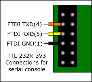
This requires some hardware. Namely a TTL-232R-3V3 or equivalent is required. The mini uart described in the AUX peripheral below is available on the RPI IO expansion headers on pins 8 (GPIO14/TXD) and 10 (GPIO15/RXD)
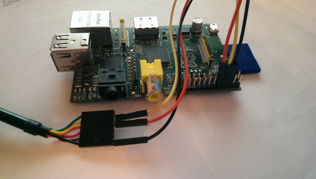
Connecting the UART to a PC is pretty easy, a quick connection guide is available:
Also, a quick photo of one connected up:
AUX peripheral
The AUX peripheral includes a couple of communication interfaces which we can put to use. In this tutorial we will enable the mini UART which has Rx/Tx signals available on the IO header of the raspberry-pi. We will connect that to an FTDI 3.3V USB->UART converter and then we can connect PuTTY to the COM port and see output from the code!
We will do some more work on the c stubs to provide uart support in the write system call which is what the likes of printf(), etc. functions use to write to the system.
/*
    Part of the Raspberry-Pi Bare Metal Tutorials
    https://www.valvers.com/rpi/bare-metal/
    Copyright (c) 2013-2018, Brian Sidebotham

    This software is licensed under the MIT License.
    Please see the LICENSE file included with this software.

*/

#include "rpi-aux.h"
#include "rpi-base.h"
#include "rpi-gpio.h"

static aux_t* auxillary = (aux_t*)AUX_BASE;


aux_t* RPI_GetAux( void )
{
    return auxillary;
}

/* Define the system clock frequency in MHz for the baud rate calculation.
   This is clearly defined on the BCM2835 datasheet errata page:
   http://elinux.org/BCM2835_datasheet_errata */


void RPI_AuxMiniUartInit( int baud, int bits )
{
    /* As this is a mini uart the configuration is complete! Now just
       enable the uart. Note from the documentation in section 2.1.1 of
       the ARM peripherals manual:

       If the enable bits are clear you will have no access to a
       peripheral. You can not even read or write the registers */
    auxillary->ENABLES = AUX_ENA_MINIUART;

    auxillary->MU_IER = 0;

    /* Disable flow control,enable transmitter and receiver! */
    auxillary->MU_CNTL = 0;

    /* Decide between seven or eight-bit mode */
    if( bits == 8 )
        auxillary->MU_LCR = AUX_MULCR_8BIT_MODE;
    else
        auxillary->MU_LCR = 0;

    auxillary->MU_MCR = 0;

    /* Disable all interrupts from MU and clear the fifos */
    auxillary->MU_IER = 0;

    auxillary->MU_IIR = 0xC6;

    /* Transposed calculation from Section 2.2.1 of the ARM peripherals manual */
    auxillary->MU_BAUD = ( SYSFREQ / ( 8 * baud ) ) - 1;

    /* Setup GPIO 14 and 15 as alternative function 5 which is UART 1 TXD/RXD. These need to be
       set before enabling the UART */
    RPI_SetGpioPinFunction( RPI_GPIO14, FS_ALT5 );
    RPI_SetGpioPinFunction( RPI_GPIO15, FS_ALT5 );

    /* See the requirements in the GPIO section of the timing requirements of the GPIO controller.
       Who knows why 150 cycles is mentioned - what if we're running at 1500MHz as opposed to
       500MHz ? */
    RPI_GetGpio()->GPPUD = 0;
    for( volatile int i=0; i<150; i++ ) { }
    RPI_GetGpio()->GPPUDCLK0 = ( 1 << 14 );
    for( volatile int i=0; i<150; i++ ) { }
    RPI_GetGpio()->GPPUDCLK0 = 0;

    /* Disable flow control,enable transmitter and receiver! */
    auxillary->MU_CNTL = AUX_MUCNTL_TX_ENABLE;
}


void RPI_AuxMiniUartWrite( char c )
{
    /* Wait until the UART has an empty space in the FIFO */
    while( ( auxillary->MU_LSR & AUX_MULSR_TX_EMPTY ) == 0 ) { }

    /* Write the character to the FIFO for transmission */
    auxillary->MU_IO = c;
}
/*
    Part of the Raspberry-Pi Bare Metal Tutorials
    https://www.valvers.com/rpi/bare-metal/
    Copyright (c) 2013-2018, Brian Sidebotham

    This software is licensed under the MIT License.
    Please see the LICENSE file included with this software.

*/

#ifndef RPI_AUX_H
#define RPI_AUX_H

#include "rpi-base.h"

/* Although these values were originally from the BCM2835 Arm peripherals PDF
   it's clear that was rushed and has some glaring errors - so these values
   may appear to be different. These values have been changed due to data on
   the elinux BCM2835 datasheet errata:
   http://elinux.org/BCM2835_datasheet_errata */

#define AUX_BASE    ( PERIPHERAL_BASE + 0x215000 )

#define AUX_ENA_MINIUART            ( 1 << 0 )
#define AUX_ENA_SPI1                ( 1 << 1 )
#define AUX_ENA_SPI2                ( 1 << 2 )

#define AUX_IRQ_SPI2                ( 1 << 2 )
#define AUX_IRQ_SPI1                ( 1 << 1 )
#define AUX_IRQ_MU                  ( 1 << 0 )

#define AUX_MULCR_8BIT_MODE         ( 3 << 0 )  /* See errata for this value */
#define AUX_MULCR_BREAK             ( 1 << 6 )
#define AUX_MULCR_DLAB_ACCESS       ( 1 << 7 )

#define AUX_MUMCR_RTS               ( 1 << 1 )

#define AUX_MULSR_DATA_READY        ( 1 << 0 )
#define AUX_MULSR_RX_OVERRUN        ( 1 << 1 )
#define AUX_MULSR_TX_EMPTY          ( 1 << 5 )
#define AUX_MULSR_TX_IDLE           ( 1 << 6 )

#define AUX_MUMSR_CTS               ( 1 << 5 )

#define AUX_MUCNTL_RX_ENABLE        ( 1 << 0 )
#define AUX_MUCNTL_TX_ENABLE        ( 1 << 1 )
#define AUX_MUCNTL_RTS_FLOW         ( 1 << 2 )
#define AUX_MUCNTL_CTS_FLOW         ( 1 << 3 )
#define AUX_MUCNTL_RTS_FIFO         ( 3 << 4 )
#define AUX_MUCNTL_RTS_ASSERT       ( 1 << 6 )
#define AUX_MUCNTL_CTS_ASSERT       ( 1 << 7 )

#define AUX_MUSTAT_SYMBOL_AV        ( 1 << 0 )
#define AUX_MUSTAT_SPACE_AV         ( 1 << 1 )
#define AUX_MUSTAT_RX_IDLE          ( 1 << 2 )
#define AUX_MUSTAT_TX_IDLE          ( 1 << 3 )
#define AUX_MUSTAT_RX_OVERRUN       ( 1 << 4 )
#define AUX_MUSTAT_TX_FIFO_FULL     ( 1 << 5 )
#define AUX_MUSTAT_RTS              ( 1 << 6 )
#define AUX_MUSTAT_CTS              ( 1 << 7 )
#define AUX_MUSTAT_TX_EMPTY         ( 1 << 8 )
#define AUX_MUSTAT_TX_DONE          ( 1 << 9 )
#define AUX_MUSTAT_RX_FIFO_LEVEL    ( 7 << 16 )
#define AUX_MUSTAT_TX_FIFO_LEVEL    ( 7 << 24 )


#define FSEL0(x)        ( x )
...
#define FSEL53(x)       ( x << 9 )


typedef struct {
    volatile unsigned int IRQ;
    volatile unsigned int ENABLES;

    volatile unsigned int reserved1[((0x40 - 0x04) / 4) - 1];

    volatile unsigned int MU_IO;
    volatile unsigned int MU_IER;
    volatile unsigned int MU_IIR;
    volatile unsigned int MU_LCR;
    volatile unsigned int MU_MCR;
    volatile unsigned int MU_LSR;
    volatile unsigned int MU_MSR;
    volatile unsigned int MU_SCRATCH;
    volatile unsigned int MU_CNTL;
    volatile unsigned int MU_STAT;
    volatile unsigned int MU_BAUD;

    volatile unsigned int reserved2[(0x80 - 0x68) / 4];

    volatile unsigned int SPI0_CNTL0;
    volatile unsigned int SPI0_CNTL1;
    volatile unsigned int SPI0_STAT;
    volatile unsigned int SPI0_IO;
    volatile unsigned int SPI0_PEEK;

    volatile unsigned int reserved3[(0xC0 - 0x94) / 4];

    volatile unsigned int SPI1_CNTL0;
    volatile unsigned int SPI1_CNTL1;
    volatile unsigned int SPI1_STAT;
    volatile unsigned int SPI1_IO;
    volatile unsigned int SPI1_PEEK;
    } aux_t;

extern aux_t* RPI_GetAux( void );
extern void RPI_AuxMiniUartInit( int baud, int bits );
extern void RPI_AuxMiniUartWrite( char c );

#endif
I'm not going to go too far into explaining these drivers now. It's written in C, and you've got the BCM2835 data sheet the same as I have. You should be getting familiar with the layout of these "driver" files and the documentation in the BCM2835 peripherals document.
We provide an initialisation function so we can set the number of bits (data bits) and the baud rate. The mini UART implementation isn't that configurable because it's not a full UART implementation. It's designed to provide a quick means of providing a console with as little code as possible. So there's no setting for parity or number of stop bits. It's always N1 (No parity, one stop bit).
HACK: The calculation for the baud rate registers is done based on a defined system frequency relative to the RPI type. It works, but it's not as nice as using a programatically detected system frequency.
The functions are written in a blocking mode, so the write function blocks until the UART can accept the next character, then it writes the new character and returns. Normally we'd use the UART interrupt to send a whole buffer of data rather than manually polling the register as this ties the processor up waiting. However, these are easy to use!
The _write() System Call
Whenever data needs to be written to the OS it's done so through a function called _write. This is one of the original c-stubs we wrote in a previous tutorial. We previously just implemented a blank function. Here's the blank function we had. As you can see, it's not quite blank, but outbyte does nothing with the data, it's an empty sink.
void outbyte( char b )
{
    (void)b;
}

int _write( int file, char *ptr, int len )
{
    int todo;

    for( todo = 0; todo < len; todo++ )
      outbyte(*ptr++);

    return len;
}
We can tie all writes to the OS (for all files) to the UART console by adding the UART write function call to outbyte:
Originally this is what I did, and then when I used printf() to test function I kept getting a crash. In fact after some debugging with the OK LED in the processor exception handlers we introduced in the last tutorial I was able to determine it was an undefined instruction error.
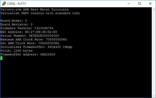
When you run this tutorials examples with PuTTY, you'll see output similar to this:
If you're on Linux, you can use screen to view the output of the tutorial in the terminal:
NOTE: You may have to use sudo in order to open the USB tty!
Enabling VFP Support
After a bit more thinking and tinkering I realised we have to enable the VFP now in order to use printf. As we're compiling and telling the compiler (or more the linker actually) that we're targeting a device with the VFP it is linking to a libc that can use VFP instructions and why shouldn't something in the printf implementation use the VFP instruction when necessary to speed things up?
There is some more information about the problem on a stackoverflow answer.
Without the VFP co-processor being enabled, VFP instructions will cause an undefined instruction exception. Enabling the VFP is another task that the C Runtime startup file crt0 would have performed for us, but we're on our own since we have to use -nostartfiles (See an earlier tutorial).
Some recommended information about enabling VFP support is available from ARM.
Some example code for enabling the VFP is available on the TI wiki, and that's the code we slice in to armc-start.S so that the VFP is enabled before the c library is setup:
// Enable VFP ------------------------------------------------------------

// r1 = Access Control Register
MRC p15, #0, r1, c1, c0, #2
// enable full access for p10,11
ORR r1, r1, #(0xf << 20)
// ccess Control Register = r1
MCR p15, #0, r1, c1, c0, #2
MOV r1, #0
// flush prefetch buffer because of FMXR below
MCR p15, #0, r1, c7, c5, #4
// and CP 10 & 11 were only just enabled
// Enable VFP itself
MOV r0,#0x40000000
// FPEXC = r0
FMXR FPEXC, r0
With those additions, we can now go ahead and use the c-library write functions. It means that the full printf() implementation can be used on the UART for example without us having to lift a finger and try and implement something as fundamental as that ourselves.
Also, this provides us with a debug/comms channel that is separate to the display. It's hard to use the display for debugging when the display isn't yet working!
Mailboxes
We introduce some code in a few files, namely rpi-mailbox and rpi-mailbox-interface. The first is a common interface to access the mailbox system which passes information from the GPU to the ARM processor. The mailbox interface is implemented in the firmware (start.elf) that runs on the GPU.
Here's the code, and as noted in the comments, the mailbox interface is described on the RPI firmware github wiki:
rpi-mailbox.h
#ifndef RPI_MAILBOX_H
#define RPI_MAILBOX_H

#include "rpi-base.h"

#define RPI_MAILBOX0_BASE    ( PERIPHERAL_BASE + 0xB880 )

/* The available mailbox channels in the BCM2835 Mailbox interface.
   See https://github.com/raspberrypi/firmware/wiki/Mailboxes for
   information */
typedef enum {
    MB0_POWER_MANAGEMENT = 0,
    MB0_FRAMEBUFFER,
    MB0_VIRTUAL_UART,
    MB0_VCHIQ,
    MB0_LEDS,
    MB0_BUTTONS,
    MB0_TOUCHSCREEN,
    MB0_UNUSED,
    MB0_TAGS_ARM_TO_VC,
    MB0_TAGS_VC_TO_ARM,
} mailbox0_channel_t;

/* These defines come from the Broadcom Videocode driver source code, see:
   brcm_usrlib/dag/vmcsx/vcinclude/bcm2708_chip/arm_control.h */
enum mailbox_status_reg_bits {
    ARM_MS_FULL  = 0x80000000,
    ARM_MS_EMPTY = 0x40000000,
    ARM_MS_LEVEL = 0x400000FF,
};

/* Define a structure which defines the register access to a mailbox.
   Not all mailboxes support the full register set! */
typedef struct {
    volatile unsigned int Read;
    volatile unsigned int reserved1[((0x90 - 0x80) / 4) - 1];
    volatile unsigned int Poll;
    volatile unsigned int Sender;
    volatile unsigned int Status;
    volatile unsigned int Configuration;
    volatile unsigned int Write;
    } mailbox_t;

extern void RPI_Mailbox0Write( mailbox0_channel_t channel, int value );
extern int RPI_Mailbox0Read( mailbox0_channel_t channel );

#endif
rpi-mailbox.c:
#include <stdint.h>

#include "rpi-gpio.h"
#include "rpi-mailbox.h"

/* Mailbox 0 mapped to it's base address */
static mailbox_t* rpiMailbox0 = (mailbox_t*)RPI_MAILBOX0_BASE;

void RPI_Mailbox0Write( mailbox0_channel_t channel, int value )
{
    /* For information about accessing mailboxes, see:
       https://github.com/raspberrypi/firmware/wiki/Accessing-mailboxes */

    /* Add the channel number into the lower 4 bits */
    value &= ~(0xF);
    value |= channel;

    /* Wait until the mailbox becomes available and then write to the mailbox
       channel */
    while( ( rpiMailbox0->Status & ARM_MS_FULL ) != 0 ) { }

    /* Write the modified value + channel number into the write register */
    rpiMailbox0->Write = value;
}


int RPI_Mailbox0Read( mailbox0_channel_t channel )
{
    /* For information about accessing mailboxes, see:
       https://github.com/raspberrypi/firmware/wiki/Accessing-mailboxes */
    int value = -1;

    /* Keep reading the register until the desired channel gives us a value */
    while( ( value & 0xF ) != channel )
    {
        /* Wait while the mailbox is empty because otherwise there's no value
           to read! */
        while( rpiMailbox0->Status & ARM_MS_EMPTY ) { }

        /* Extract the value from the Read register of the mailbox. The value
           is actually in the upper 28 bits */
        value = rpiMailbox0->Read;
    }

    /* Return just the value (the upper 28-bits) */
    return value >> 4;
}
There are two mailboxes, 0 and 1. We only need to use mailbox 0. Mailbox has a number of channels to communicate on which are defined in the enum mailbox0_channel_t.
The basics of the mailbox operation are pretty straight forward.
To write to a mailbox we first construct a composite value. We can write a 32-bit value to the GPU which is generally a memory address, but the mailbox also has to support multiple channels and there is no separate place to write the channel number. In order to achieve multiple channels on a single mailbox the lower nibble (4-bits) are reserved for the channel number and the upper 28-bits are the value we're sending to the GPU. This means that any address we send to the GPU is missing the lowest 4-bits and the GPU simply assumes those bits are all 0. We therefore need to align any address we send the GPU to a 16-byte boundary which will ensure the lower 4-bits will be 0.
The ARM waits for the mailbox to become empty by polling the status register and then it can write the composite value of the address and channel to the mailbox.
To read from a mailbox we wait until the mailbox is full and read the value. Only when the value contains the same channel as we are waiting to communicate with do we proceed and return.
The value is a 16-byte aligned memory address. It's important to know that we don't just send a value and get a value back. We send an address to a memory block that we have constructed specifically formatted messages in to communicate with the GPU. The messages that are passed to the GPU are channel dependant and so aren't defined in this code module. We will do a code module for each channel we use. Actually, we're only going to use one - MB0_TAGS_ARM_TO_VC which is used with the mailbox property interface.
NOTE: Although the Framebuffer channel looks like the place to begin, actually we'll ignore that mailbox channel because it's a deprecated channel. It came before the mailbox property interface channel had framebuffer properties added to it.
Mailbox Property Interface
The Mailbox Property Interface specifies the messaging structure that needs to be present in the 16-byte aligned memory region I mentioned earlier. There are a lot of properties, and you need to read that page a couple of times to get a hold of how the data needs to be laid out.
Here's the code we're using to support the Mailbox Property Interface:
rpi-mailbox-interface.c:
#include <stdarg.h>
#include <stdio.h>
#include <string.h>

#include "rpi-mailbox.h"
#include "rpi-mailbox-interface.h"

/* Make sure the property tag buffer is aligned to a 16-byte boundary because
   we only have 28-bits available in the property interface protocol to pass
   the address of the buffer to the VC. */
static int pt[8192] __attribute__((aligned(16)));
static int pt_index = 0;


void RPI_PropertyInit( void )
{
    /* Fill in the size on-the-fly */
    pt[PT_OSIZE] = 12;

    /* Process request (All other values are reserved!) */
    pt[PT_OREQUEST_OR_RESPONSE] = 0;

    /* First available data slot */
    pt_index = 2;

    /* NULL tag to terminate tag list */
    pt[pt_index] = 0;
}

/**
    @brief Add a property tag to the current tag list. Data can be included. All data is uint32_t
    @param tag
*/
void RPI_PropertyAddTag( rpi_mailbox_tag_t tag, ... )
{
    va_list vl;
    va_start( vl, tag );

    pt[pt_index++] = tag;

    switch( tag )
    {
        case TAG_GET_FIRMWARE_VERSION:
        case TAG_GET_BOARD_MODEL:
        case TAG_GET_BOARD_REVISION:
        case TAG_GET_BOARD_MAC_ADDRESS:
        case TAG_GET_BOARD_SERIAL:
        case TAG_GET_ARM_MEMORY:
        case TAG_GET_VC_MEMORY:
        case TAG_GET_DMA_CHANNELS:
            /* Provide an 8-byte buffer for the response */
            pt[pt_index++] = 8;
            pt[pt_index++] = 0; /* Request */
            pt_index += 2;
            break;

        case TAG_GET_CLOCKS:
        case TAG_GET_COMMAND_LINE:
            /* Provide a 256-byte buffer */
            pt[pt_index++] = 256;
            pt[pt_index++] = 0; /* Request */
            pt_index += 256 >> 2;
            break;

        case TAG_ALLOCATE_BUFFER:
        case TAG_GET_MAX_CLOCK_RATE:
        case TAG_GET_MIN_CLOCK_RATE:
        case TAG_GET_CLOCK_RATE:
            pt[pt_index++] = 8;
            pt[pt_index++] = 0; /* Request */
            pt[pt_index++] = va_arg( vl, int );
            pt[pt_index++] = 0;
            break;

        case TAG_SET_CLOCK_RATE:
            pt[pt_index++] = 12;
            pt[pt_index++] = 0; /* Request */
            pt[pt_index++] = va_arg( vl, int ); /* Clock ID */
            pt[pt_index++] = va_arg( vl, int ); /* Rate (in Hz) */
            pt[pt_index++] = va_arg( vl, int ); /* Skip turbo setting if == 1 */
            break;

        case TAG_GET_PHYSICAL_SIZE:
        case TAG_SET_PHYSICAL_SIZE:
        case TAG_TEST_PHYSICAL_SIZE:
        case TAG_GET_VIRTUAL_SIZE:
        case TAG_SET_VIRTUAL_SIZE:
        case TAG_TEST_VIRTUAL_SIZE:
        case TAG_GET_VIRTUAL_OFFSET:
        case TAG_SET_VIRTUAL_OFFSET:
            pt[pt_index++] = 8;
            pt[pt_index++] = 0; /* Request */

            if( ( tag == TAG_SET_PHYSICAL_SIZE ) ||
                ( tag == TAG_SET_VIRTUAL_SIZE ) ||
                ( tag == TAG_SET_VIRTUAL_OFFSET ) ||
                ( tag == TAG_TEST_PHYSICAL_SIZE ) ||
                ( tag == TAG_TEST_VIRTUAL_SIZE ) )
            {
                pt[pt_index++] = va_arg( vl, int ); /* Width */
                pt[pt_index++] = va_arg( vl, int ); /* Height */
            }
            else
            {
                pt_index += 2;
            }
            break;

        case TAG_GET_ALPHA_MODE:
        case TAG_SET_ALPHA_MODE:
        case TAG_GET_DEPTH:
        case TAG_SET_DEPTH:
        case TAG_GET_PIXEL_ORDER:
        case TAG_SET_PIXEL_ORDER:
        case TAG_GET_PITCH:
            pt[pt_index++] = 4;
            pt[pt_index++] = 0; /* Request */

            if( ( tag == TAG_SET_DEPTH ) ||
                ( tag == TAG_SET_PIXEL_ORDER ) ||
                ( tag == TAG_SET_ALPHA_MODE ) )
            {
                /* Colour Depth, bits-per-pixel \ Pixel Order State */
                pt[pt_index++] = va_arg( vl, int );
            }
            else
            {
                pt_index += 1;
            }
            break;

        case TAG_GET_OVERSCAN:
        case TAG_SET_OVERSCAN:
            pt[pt_index++] = 16;
            pt[pt_index++] = 0; /* Request */

            if( ( tag == TAG_SET_OVERSCAN ) )
            {
                pt[pt_index++] = va_arg( vl, int ); /* Top pixels */
                pt[pt_index++] = va_arg( vl, int ); /* Bottom pixels */
                pt[pt_index++] = va_arg( vl, int ); /* Left pixels */
                pt[pt_index++] = va_arg( vl, int ); /* Right pixels */
            }
            else
            {
                pt_index += 4;
            }
            break;

        default:
            /* Unsupported tags, just remove the tag from the list */
            pt_index--;
            break;
    }

    /* Make sure the tags are 0 terminated to end the list and update the buffer size */
    pt[pt_index] = 0;

    va_end( vl );
}


int RPI_PropertyProcess( void )
{
    int result;

#if( PRINT_PROP_DEBUG == 1 )
    printf( "%s Length: %d\r\n", __func__, pt[PT_OSIZE] );
#endif
    /* Fill in the size of the buffer */
    pt[PT_OSIZE] = ( pt_index + 1 ) << 2;
    pt[PT_OREQUEST_OR_RESPONSE] = 0;

#if( PRINT_PROP_DEBUG == 1 )
    for( i = 0; i < (pt[PT_OSIZE] >> 2); i++ )
        printf( "Request: %3d %8.8X\r\n", i, pt[i] );
#endif
    RPI_Mailbox0Write( MB0_TAGS_ARM_TO_VC, (unsigned int)pt );

    result = RPI_Mailbox0Read( MB0_TAGS_ARM_TO_VC );

#if( PRINT_PROP_DEBUG == 1 )
    for( i = 0; i < (pt[PT_OSIZE] >> 2); i++ )
        printf( "Response: %3d %8.8X\r\n", i, pt[i] );
#endif
    return result;
}


rpi_mailbox_property_t* RPI_PropertyGet( rpi_mailbox_tag_t tag )
{
    static rpi_mailbox_property_t property;
    int* tag_buffer = NULL;

    property.tag = tag;

    /* Get the tag from the buffer. Start at the first tag position  */
    int index = 2;

    while( index < ( pt[PT_OSIZE] >> 2 ) )
    {
        /* printf( "Test Tag: [%d] %8.8X\r\n", index, pt[index] ); */
        if( pt[index] == tag )
        {
            tag_buffer = &pt[index];
            break;
        }

        /* Progress to the next tag if we haven't yet discovered the tag */
        index += ( pt[index + 1] >> 2 ) + 3;
    }

    /* Return NULL of the property tag cannot be found in the buffer */
    if( tag_buffer == NULL )
        return NULL;

    /* Return the required data */
    property.byte_length = tag_buffer[T_ORESPONSE] & 0xFFFF;
    memcpy( property.data.buffer_8, &tag_buffer[T_OVALUE], property.byte_length );

    return &property;
}
#ifndef RPI_MAILBOX_INTERFACE_H
#define RPI_MAILBOX_INTERFACE_H

/**
    @brief An enum of the RPI->Videocore firmware mailbox property interface
    properties. Further details are available from
    https://github.com/raspberrypi/firmware/wiki/Mailbox-property-interface
*/
typedef enum {
    /* Videocore */
    TAG_GET_FIRMWARE_VERSION = 0x1,

    /* Hardware */
    TAG_GET_BOARD_MODEL = 0x10001,
    TAG_GET_BOARD_REVISION,
    TAG_GET_BOARD_MAC_ADDRESS,
    TAG_GET_BOARD_SERIAL,
    TAG_GET_ARM_MEMORY,
    TAG_GET_VC_MEMORY,
    TAG_GET_CLOCKS,

    /* Config */
    TAG_GET_COMMAND_LINE = 0x50001,

    /* Shared resource management */
    TAG_GET_DMA_CHANNELS = 0x60001,

    /* Power */
    TAG_GET_POWER_STATE = 0x20001,
    TAG_GET_TIMING,
    TAG_SET_POWER_STATE = 0x28001,

    /* Clocks */
    TAG_GET_CLOCK_STATE = 0x30001,
    TAG_SET_CLOCK_STATE = 0x38001,
    TAG_GET_CLOCK_RATE = 0x30002,
    TAG_SET_CLOCK_RATE = 0x38002,
    TAG_GET_MAX_CLOCK_RATE = 0x30004,
    TAG_GET_MIN_CLOCK_RATE = 0x30007,
    TAG_GET_TURBO = 0x30009,
    TAG_SET_TURBO = 0x38009,

    /* Voltage */
    TAG_GET_VOLTAGE = 0x30003,
    TAG_SET_VOLTAGE = 0x38003,
    TAG_GET_MAX_VOLTAGE = 0x30005,
    TAG_GET_MIN_VOLTAGE = 0x30008,
    TAG_GET_TEMPERATURE = 0x30006,
    TAG_GET_MAX_TEMPERATURE = 0x3000A,
    TAG_ALLOCATE_MEMORY = 0x3000C,
    TAG_LOCK_MEMORY = 0x3000D,
    TAG_UNLOCK_MEMORY = 0x3000E,
    TAG_RELEASE_MEMORY = 0x3000F,
    TAG_EXECUTE_CODE = 0x30010,
    TAG_GET_DISPMANX_MEM_HANDLE = 0x30014,
    TAG_GET_EDID_BLOCK = 0x30020,

    /* Framebuffer */
    TAG_ALLOCATE_BUFFER = 0x40001,
    TAG_RELEASE_BUFFER = 0x48001,
    TAG_BLANK_SCREEN = 0x40002,
    TAG_GET_PHYSICAL_SIZE = 0x40003,
    TAG_TEST_PHYSICAL_SIZE = 0x44003,
    TAG_SET_PHYSICAL_SIZE = 0x48003,
    TAG_GET_VIRTUAL_SIZE = 0x40004,
    TAG_TEST_VIRTUAL_SIZE = 0x44004,
    TAG_SET_VIRTUAL_SIZE = 0x48004,
    TAG_GET_DEPTH = 0x40005,
    TAG_TEST_DEPTH = 0x44005,
    TAG_SET_DEPTH = 0x48005,
    TAG_GET_PIXEL_ORDER = 0x40006,
    TAG_TEST_PIXEL_ORDER = 0x44006,
    TAG_SET_PIXEL_ORDER = 0x48006,
    TAG_GET_ALPHA_MODE = 0x40007,
    TAG_TEST_ALPHA_MODE = 0x44007,
    TAG_SET_ALPHA_MODE = 0x48007,
    TAG_GET_PITCH = 0x40008,
    TAG_GET_VIRTUAL_OFFSET = 0x40009,
    TAG_TEST_VIRTUAL_OFFSET = 0x44009,
    TAG_SET_VIRTUAL_OFFSET = 0x48009,
    TAG_GET_OVERSCAN = 0x4000A,
    TAG_TEST_OVERSCAN = 0x4400A,
    TAG_SET_OVERSCAN = 0x4800A,
    TAG_GET_PALETTE = 0x4000B,
    TAG_TEST_PALETTE = 0x4400B,
    TAG_SET_PALETTE = 0x4800B,
    TAG_SET_CURSOR_INFO = 0x8011,
    TAG_SET_CURSOR_STATE = 0x8010

    } rpi_mailbox_tag_t;


typedef enum {
    TAG_STATE_REQUEST = 0,
    TAG_STATE_RESPONSE = 1,
    } rpi_tag_state_t;


typedef enum {
    PT_OSIZE = 0,
    PT_OREQUEST_OR_RESPONSE = 1,
    } rpi_tag_buffer_offset_t;

typedef enum {
    T_OIDENT = 0,
    T_OVALUE_SIZE = 1,
    T_ORESPONSE = 2,
    T_OVALUE = 3,
    } rpi_tag_offset_t;

typedef struct {
    int tag;
    int byte_length;
    union {
        int value_32;
        unsigned char buffer_8[256];
        int buffer_32[64];
    } data;
    } rpi_mailbox_property_t;

typedef enum {
    TAG_CLOCK_RESERVED = 0,
    TAG_CLOCK_EMMC,
    TAG_CLOCK_UART,
    TAG_CLOCK_ARM,
    TAG_CLOCK_CORE,
    TAG_CLOCK_V3D,
    TAG_CLOCK_H264,
    TAG_CLOCK_ISP,
    TAG_CLOCK_SDRAM,
    TAG_CLOCK_PIXEL,
    TAG_CLOCK_PWM,
    } rpi_tag_clock_id_t;

extern void RPI_PropertyInit( void );
extern void RPI_PropertyAddTag( rpi_mailbox_tag_t tag, ... );
extern int RPI_PropertyProcess( void );
extern rpi_mailbox_property_t* RPI_PropertyGet( rpi_mailbox_tag_t tag );

#endif
NOTE: As you can see, I've left some debugging
printf()calls in so you can choose to print them out - this means it'll print out the buffer you message the GPU with and see the resulting buffer when the GPU has finished it's response
We start off with a memory buffer which is large enough to hold a concatenated list of property tags and data for the property tags we want to use. We use a gcc extension to align it to a 16-byte boundary:
The rest of the functions form a C API to the Mailbox Property Interface. There are various APIs people come up with to generate the memory structure.
The messages are constructed such that the data length is large enough for whichever is larger, the message request data size or the response data size. It's also good to note that so long as the data size is large enough the GPU will be happy. i.e. you can use a larger data size for the tag and the GPU won't complain. As you can see from the void RPI_PropertyAddTag( rpi_mailbox_tag_t tag, ... ) switch tag statement there are only a few types of tag layout anyway.
The GPU acts upon tag values which have the request/response code set to process request settings (always 0). When the GPU has parsed a value and filled the tag's value buffer with the value required it sets the request/response indicator to 1 to show that the data in the value buffer is the GPU's response. All of this modifies the data in-place.
The API I wrote for this tutorial allows us to have a simple paradime for using the property interface.
/* Initialise, Add and Process tags */
RPI_PropertyInit();
RPI_PropertyAddTag( TAG_*, ... );
RPI_PropertyAddTag( TAG_*, ... );
RPI_PropertyAddTag( TAG_*, ... );
RPI_PropertyProcess();

/* Get the value for each tag */
property_value_buffer = RPI_PropertyGet( TAG_* );
The Framebuffer Properties
If you don't yet know, a framebuffer is a block of memory who's data is written to a display. The data organisation depends on the display's attributes such as width, height, colour depth, etc. There is not usually a conversion between one type of data and the framebuffer. The GPU simply clocks the data in the framebuffer to the display.
If a monitor is plugged in to the Raspberry-Pi the GPU detects it and displays a colour gradiant square on the screen. This shows that the RPI is up and running and has detected the screen.
Through the mailbox property interface we can negotiate with the GPU so that it creates a framebuffer in memory that is of the correct size to represent the screen attached (or the size of the virtual screen we've requested). It will return a pointer to that memory so that the ARM has memory it can write to that will be directly written to the screen by the GPU. It's the most basic and simplest form of graphics. Each pixel's colour can be controlled by writing data into the buffer.
Let's look at how we use the property interface to negotiate a 32-bit framebuffer at 1280x1024:
/* Initialise a framebuffer... */
RPI_PropertyInit();
RPI_PropertyAddTag( TAG_ALLOCATE_BUFFER );
RPI_PropertyAddTag( TAG_SET_PHYSICAL_SIZE, 1280, 1024 );
RPI_PropertyAddTag( TAG_SET_VIRTUAL_SIZE, 1280, 2048 );
RPI_PropertyAddTag( TAG_SET_DEPTH, 32 );
RPI_PropertyAddTag( TAG_GET_PITCH );
RPI_PropertyAddTag( TAG_GET_PHYSICAL_SIZE );
RPI_PropertyAddTag( TAG_GET_DEPTH );
RPI_PropertyProcess();
As you can see, we set up a load of tags for the GPU to process. We ask it to allocate a framebuffer, so set the physical and virtual size of the screen, and the colour depth. We then also ask it to return us some information, the current pitch, the physical size and the colour depth.
The mailbox interface guarantees that the SET_* tags will be completed before the GET_* tags are processed so we can do a single process with all of the tags in place. Some of the SET_* tags may not be able to achieve what we ask for and so we must use the GET_* tags to know what the framebuffer settings actually are.
The reason there is a physical and virtual size (and why they are set differently!) is because the virtual size can be larger than the physical size where the physical is "mapped" to a part of the framebuffer. The framebuffer is made to hold the largest of the two (which is invariably the virtual size).
In the code I've made the virtual size twice the height of the physical size. There are other mailbox properties that allow us to set an offset where the physical screen will begin in the framebuffer. You can think of the virtual as being the framebuffer and the physical as the screen. We can draw to a larger framebuffer in a region that's off the physical screen and then offset the physical screen to the area of the framebuffer we've drawn to and the update to the screen is instant rather than updating as we draw which usually shows artifacts.
For now, we just initialise the framebuffer (using the code above) and then write to the framebuffer space within the limits of the physical size. We draw a colour gradient box like the GPU does on power-on, but we "animate" it by continuously altering the colour vectors and re-drawing the screen. We use 100% of the CPU processing time to draw and you'll see just how slow this is!
Go ahead and run the example. You can spend some time changing the colour depth setting and screen size to see the performance of the framebuffer fill. You'll notice it's a lot slower than you'd realise to refresh the screen when every pixel is written to.
This is the code that does the actual draw to the framebuffer:
/* Produce a colour spread across the screen */
for( int y = 0; y < height; y++ )
{
    int line_offset = y * width;

    for( int x = 0; x < width; x++ )
    {
        fb[line_offset + x] = pixel_value++;
    }
}
We've stuck with 32 bits per pixel (previously this tutorial had an option). This simplifies the framebuffer drawing and we can see here what we're doing is really simple. All we're interested in is how fast we can write to the screen when modifying every pixel.
The pixel offset calculation can be done based on the bpp (bits-per-pixel) or colour depth setting and the number of pixels per line. We're using the width and calculating the start of the next line based on the exact memory size taken up by the pixel data.
This isn't entirely right however, because the GPU can choose to optimise the number of bytes per pixel row. The GPU refers to this as the pitch and is returned through the property interface. We should really use that when we move to an option for lower bits per pixel.
The framebuffer memory is organised with the top left pixel being at offset 0, in screen coordinates this is 0,0. Bottom right is coordinate width-1,height-1.
part-5/armc-014
This example expands on the previous part-4 interrupts code and introduces the mailbox API to negotiate a framebuffer with the GPU. It then draws an ever-changing colour square on the screen which changes colour to animate the display. The Frames Per Second (FPS) is also calculated and sent to the mini UART so if you're monitoring the UART with a terminal such as PuTTY you'll be able to see the FPS calculated live on your Pi.
While we acheive that, this does demonstrate how slow software rendering is. The framebuffer is set to 640x480 so that the demo will work on every HDMI panel that's plugged in. 640x480 is not exactly a big screen and yet below are the Frames Per Second (FPS) we managed to achieve on the RPI1 and RPI2.
In order to calculate the frames per second, we need to know how long a second is. We therefore use the following code to determine the core frequency so we can calculate the required timer interrupt speed. The BCM2385 peripherals datasheet refers to the APB clock which is the same as the core clock.
The code is a bit messy, but it gets the job done so no matter the rpi we're running on, or the current core frequency, we'll get the right timer interrupt rate. We use this interrupt rate to keep track of the uptime in seconds and blinking the LED at 2Hz.
/* Use the GPU Mailbox to dynamically retrieve the CORE Clock Frequency. This is also what the
   datasheet refers to as the APB (Advanced Peripheral Bus) clock which drives the ARM Timer
   peripheral */
RPI_PropertyInit();
RPI_PropertyAddTag(TAG_GET_CLOCK_RATE, TAG_CLOCK_CORE);
RPI_PropertyProcess();
mp = RPI_PropertyGet(TAG_GET_CLOCK_RATE);
uint32_t core_frequency = mp->data.buffer_32[1];

/* Calculate the timer reload register value so we achieve an interrupt rate of 2Hz. Every
   second interrupt will therefore be one second. It's approximate, the division doesn't
   really work out to be precisely 1s because of the divisor options and the core
   frequency. */
uint16_t prescales[] = {1, 16, 256, 1};
uint32_t timer_load = (1.0 / 2) / (1.0/(core_frequency / (RPI_GetArmTimer()->PreDivider + 1) * (prescales[(RPI_GetArmTimer()->Control & 0xC) >> 2])));
RPI_GetArmTimer()->Load = timer_load;
Run the code and you'll get some continually changing output on the UART console that shows you the board revision, clock speeds and the currently calculated Frames Per Second (FPS) achieve.
------------------------------------------
Valvers.com ARM Bare Metal Tutorials
Initialise UART console with standard libc
CORE Frequency: 200MHz
ARM  Frequency: 600MHz
Board Revision: 0x00b03111 rpi-4B BCM2711 2GiB Sony UK
Firmware Version: 1593701958
MAC Address: DC:A6:32:02:DB:E0
Serial Number: C2702EF910000000
Initialised Framebuffer: 640x480 32bpp
Pitch: 2560 bytes
Framebuffer address: 3E9A2000
Results
Here's some tabulated results about the ARM frequency (with no settings in config.txt) for the various boards I'm working with and the Frames Per Second (FPS) they all acheived:
| Model | FPS | CORE Frequency | ARM Frequency | Board Revision |
|---|---|---|---|---|
| RPI0 | 5.21 | 250MHz | 700MHz | 0x00900092 rpi-Zero BCM2835 512MB Sony UK |
| RPI1B+ | 5.05 | 250MHz | 700MHz | 0x00000010 rpi-1B+ BCM2835 |
| RPI2 | 2.30 | 250MHz | 600MHz | 0x00a01041 rpi-2B BCM2836 1GiB Sony UK |
| RPI3B | 2.26 | 250MHz | 600MHz | 0x00a02082 rpi-3B BCM2837 1GiB Sony UK |
| RPI4 | 2.77 | 200MHz | 600MHz | 0x00b03111 rpi-4B BCM2711 2GiB Sony UK |
NOTE: The RPI3B I have doesn't flash its LED because it's not a B+ where the ACK LED was moved back to a GPIO pin. So on my model the ACK LED is attached to an IO expander and is meant to be accessed through the GPU mailbox interface! I just compiled with
./build.sh rpi3bp
Those results are the right way round, I promise - the RPI0 appears to be the winner here against all the other competition! It's time for us to do some thinking and some optimising...
part-5/armc-015
In the RPI processor (all models) there is a cache system which is disabled by default and is designed to speed the processor up by enabling code to be (hopefully) run from the cache.
In this example we enable the L1 cache in the armc-start.S startup file and programatically set the ARM frequency to the maximum it's allowed to be (without overclocking). This is the only change we're going to make to see if we see any worthwhile gain in enabling this layer.
Enabling Cache
.equ    SCTLR_ENABLE_DATA_CACHE         0x4
.equ    SCTLR_ENABLE_BRANCH_PREDICTION  0x800
.equ    SCTLR_ENABLE_INSTRUCTION_CACHE  0x1000

// Enable L1 Cache -------------------------------------------------------

// R0 = System Control Register
mrc p15,0,r0,c1,c0,0

// Enable caches and branch prediction
orr r0,#SCTLR_ENABLE_BRANCH_PREDICTION
orr r0,#SCTLR_ENABLE_DATA_CACHE
orr r0,#SCTLR_ENABLE_INSTRUCTION_CACHE

// System Control Register = R0
mcr p15,0,r0,c1,c0,0
Look to the ARMv7-a architecture manual for information on enabling L1 Cache. L1 cache is closest to the processor and so is what we're interesting in enabling first off.
Let's go through the code we've added so we know why we've added it and also why it works.
Section B6.1.86 SCTLR, System Control Register, PMSA describes the system control register
This register has some bits defined which are useful for us, namely:
I, bit[12] Instruction cache enable bit.

    This is a global enable bit for instruction caches. The possible values
    of this bit are:

    0 Instruction caches disabled.
    1 Instruction caches enabled.

    If the system does not implement any instruction caches that can be
    accessed by the processor, at any level of the memory hierarchy, this
    bit is RAZ/WI.

    If the system implements any instruction caches that can be accessed
    by the processor then it must be possible to disable them by setting
    this bit to 0.

    Cache enabling and disabling on page B2-1270 describes the effect of
    enabling the caches.

Z, bit[11] Branch prediction enable bit.

    The possible values of this bit are:

    0 Program flow prediction disabled.
    1 Program flow prediction enabled.

    Setting this bit to 1 enables branch prediction, also called program
    flow prediction.

    If program flow prediction cannot be disabled, this bit is RAO/WI.
    If the implementation does not support program flow prediction then
    this bit is RAZ/WI.

C, bit[2] Cache enable bit.

    This is a global enable bit for data and unified caches. The possible
    values of this bit are:

    0 Data and unified caches disabled.
    1 Data and unified caches enabled.

    If the system does not implement any data or unified caches that can
    be accessed by the processor, at any level of the memory hierarchy,
    this bit is RAZ/WI.

    If the system implements any data or unified caches that can be
    accessed by the processor then it must be possible to disable them by
    setting this bit to 0.

For more information about the effect of this bit see Cache enabling and
disabling on page B2-1270.
In the ARMv6 Architecture Manual for the Pi1 we see:
Section B3.4 Register 1:Control registers which also descibes the system control register
This control register implements bits in the register we're interested in for enabling L1 cache:
I (bit[12])

    If separate L1 caches are used, this is the enable/disable bit for the L1
    instruction cache:

    0 = L1 instruction cache disabled
    1 = L1 instruction cache enabled.

    If an L1 unified cache is used or the L1 instruction cache is not
    implemented, this bit read as 0 and ignores writes. If the L1 instruction
    cache cannot be disabled, this bit reads as 1 and ignores writes.

    The state of this bit does not affect further levels of cache in the
    system.


Z (bit[11])

    On ARM processors which support branch prediction, this is the
    enable/disable bit for branch prediction:

    0 = Program flow prediction disabled
    1 = Program flow prediction enabled.

    If program flow prediction cannot be disabled, this bit reads as 1 and
    ignores writes.

    Program flow prediction includes all possible forms of speculative change
    of instruction stream prediction. Examples include static prediction,
    dynamic prediction, and return stacks.

    On ARM processors that do not support branch prediction, this bit reads as
    0 and ignores writes.


C (bit[2])

    If a L1 unified cache is used, this is the enable/disable bit for the
    unified cache. If separate L1 caches are used, this is the enable/disable
    bit for the data cache. In either case:

    0 = L1 unified/data cache disabled
    1 = L1 unified/data cache enabled.

    If the L1 cache is not implemented, this bit reads as 0 and ignores
    writes. If the L1 cache cannot be disabled, this bit reads as 1 and
    ignores writes.

    The state of this bit does not affect other levels of cache in the system.
As can be seen, although the cache system has changed slightly - it is essentially the same for us to use across both RPi1 and RPi2:
Get the value of the System Control Register in R0
// Enable L1 Cache -------------------------------------------------------

// R0 = System Control Register
mrc p15,0,r0,c1,c0,0
Enable the three cache bits we just identified in the architecture manuals above:
// Enable caches and branch prediction
orr r0,#SCTLR_ENABLE_BRANCH_PREDICTION
orr r0,#SCTLR_ENABLE_DATA_CACHE
orr r0,#SCTLR_ENABLE_INSTRUCTION_CACHE
Write the modified value back to the System Control Register:
Maxmising the Clock Speed
I also added in some more mailbox properties to make the RPI2 run faster. When the RPI2 starts executing code from the ARM the ARM is running at 600MHz which is a way below its 900MHz maximum. Using the mailbox properties interface we can both ask the GPU for the ARMs maximum frequency and then set the ARM frequency to the maximum returned by the GPU:
mp = RPI_PropertyGet( TAG_GET_MAX_CLOCK_RATE );

RPI_PropertyInit();
RPI_PropertyAddTag( TAG_SET_CLOCK_RATE, TAG_CLOCK_ARM, mp->data.buffer_32[1] );
RPI_PropertyProcess();
Both the above are fairly easy pickings for making sure we're getting the best speed available out of the processors, yet it was still a bit of work to get the gains!
Run armc-015 and see the gains! Here's the FPS results with No cache for comparison, don't forget that some of the ARM frequencies have changed to the maximum available here too:
| Model | FPS | FPS (L1 Cache) | Improvement | CORE Frequency | ARM Frequency | Board Revision |
|---|---|---|---|---|---|---|
| RPI0 | 5.21 | 6.86 | 1.65 | 250MHz | 1000MHz | 0x00900092 rpi-Zero BCM2835 512MB Sony UK |
| RPI1B+ | 5.05 | 5.95 | 0.9 | 250MHz | 700MHz | 0x00000010 rpi-1B+ BCM2835 |
| RPI2 | 2.30 | 3.04 | 0.74 | 250MHz | 900MHz | 0x00a01041 rpi-2B BCM2836 1GiB Sony UK |
| RPI3B | 2.26 | 3.08 | 0.82 | 250MHz | 1200MHz | 0x00a02082 rpi-3B BCM2837 1GiB Sony UK |
| RPI4 | 2.77 | 3.75 | 0.98 | 200MHz | 1500MHz | 0x00b03111 rpi-4B BCM2711 2GiB Sony UK |
Some reasonable gains, but still not exactly fast enough to start writing demos or games (Other than text-based games!). Considering some of the ARM frequency gains (+900MHz) the gains are pretty rubbish.
RPI0improves a reasonable amount from a 300MHz increase in ARM frequency and the L1 CacheRPI1B+improves slightly from just the L1 CacheRPI2improves slightly from 300MHz increase in ARM frequency and the L1 CacheRPI3B+improves a reasonable amount with 600MHz increase in ARM frequency and the L1 CacheRPI4improves a reasonable amount with the largest increase of 900MHz increase in ARM Frequency and the L1 Cache
RPI2+ Performance
At this point the question of why the RPI⅔/4 models are so much slower than the RPI1 should come to mind! I don't have the answer (Send them on a postcard please!)
The only thing going for the RPI1 is a much simpler memory system. Since the rest introduce a quad-core architecture, things got a whole bunch more complicated on the memory bus.
Anyway, let's see what else we can do.
Making the Compiler work for us
Up until now we've been working with optimisation levels -O0. Let's change that...
part-5/armc-016
One simple change to this code to see what gains can be had by the compiler. If we're using a C compiler, we really should take advantage of the fact that a massive part of it's job is to optimise the code it generates to run as fast as possible.
We'll change the optimisation level, from -O1 to -O4. Nothing else, let's see what happens to the FPS:
| Model | FPS | FPS (L1 Cache) | FPS (-O4) | Improvement | CORE Frequency | ARM Frequency | Board Revision |
|---|---|---|---|---|---|---|---|
| RPI0 | 5.21 | 6.86 | 119 | 112 | 250MHz | 1000MHz | 0x00900092 rpi-Zero BCM2835 512MB Sony UK |
| RPI1B+ | 5.05 | 5.95 | 96 | 90 | 250MHz | 700MHz | 0x00000010 rpi-1B+ BCM2835 |
| RPI2 | 2.30 | 3.04 | 139 | 136 | 250MHz | 900MHz | 0x00a01041 rpi-2B BCM2836 1GiB Sony UK |
| RPI3B | 2.26 | 3.08 | 168 | 165 | 250MHz | 1200MHz | 0x00a02082 rpi-3B BCM2837 1GiB Sony UK |
| RPI4 | 2.77 | 3.75 | 250 | 246 | 500MHz | 1500MHz | 0x00b03111 rpi-4B BCM2711 2GiB Sony UK |
Those are some impressive gains across the board! Clearly the compiler has done something essential for such big gainst. Perhaps it enables the code to entirely sit within cache or something as simple as that.
What's it done? I don't know, that's for the compiler to know and for me to find out if I can be bothered. Right now I need get on with writing code.
If you're interested in finding out, you can disassemble the code and see if you can see the major difference between an -O0 binary and an -O4 binary!
More Interesting Graphics
Back in the 90s I used to love programming demos on the Commodore Amiga 500. I loved the results. Everything was written in assembler and the tricks and cheats you used were really clever. It was a competitive environment - the moment you saw someone show a demo with something you hadn't coded you just had to get it done. It was hard!
With the RPi we have a lot of hardware in front of us - it must be possible to do some rudimentary (and ineffecient) effects.
Let's have a go:

I had this stuff lying around for quite some time before I included it in the turotial, but it moves things in a better direction - a more fun direction. I grabbed a an old demoscene style font as a GIF and use that to do actually display some graphics on the screen.
Use GIMP to save a (non-animated) GIF as a c source code. Go and find some other fonts to play with. Although this is a demoscene style font, we'll need a font to generate a console for our RPi in the upcoming tutorials, so it's worth playing around with this stuff.
The c soruce from gimp needs to be modified slightly as we need access to the struct from outside of the c file. We typedef the struct in our own header file gimp-image.h. It's all that header does.
The c source containing the image data contains 16-bit data. This 16-bit data is the same as the graphics memory in the GPU when we get a 16-bit framebuffer.
Loading and displaying images is great for working out how the graphics works at a lower level. The things we have to pay particular attention to are the number of bits per pixel for both the image data and the screen. They must match, or be transposed to match each other some how. We do this by transforming the image data to make it match that of the current dislay. This also includes getting the byte order correct so we know that the colour will be correct when it's displayed on the screen.
I've probably not been as thorough as I should be with the graphics in this tutorial code. I know that it works on my monitor with the GIF data in the tutorial though.
The code is starting to get messy - we'll need a tidy up in the next tutorial.
We have a PutPixel function now, a vertical blit (RPI_BlitV) and we also have some other functions too. We also have a standard Blit (RPI_Blit) function which are simply memory copies from the image data memory space to the video graphics memory space. I've not introduced surfaces, so we've really just got image data and the gpu data in the same format to make things as simple as possible.
NOTE: The only supported format at the moment is a 16-bit colour framebuffer. It's enough to get us going, but doesn't have alpha transparency.
In modern GPUs, we would load this font/image data up to the graphics card and the GPU would take care of blitting for us. Unfortunately we have to suffer "software rendering" which is obscenely slow in comparison. Of course, only for now - until we get some hardware acceleration going!
We don't have any hardware acceleration and we only have one thread (we have no context switching yet, and the other processors are parked). So this is all pretty inefficient.
There's no vertical sync interrupt that I've found. Instead, I've implemented delta timing in order to stick to a 50Hz refresh rate on the graphics (your mileage may vary here) so it's as flicker-free as possible.
Here's the code I've introduced (at a high level):
/* Wait 500ms to let UART to settle before we use it. The UART takes a little time to switch
   speeds. Comment out this to see some garbage at the start of the UART output if you like */
RPI_WaitMicroSeconds( 500000 );
Turns out, after we switch the baud rate of the mini uart, we need to wait a certain amount of time before using the uart as it takes a while for the baud rate change to take effect. I'm sure the wait time is more like 10-50 cycles, but it doesn't harm to wait "enough" time.
We "normalise" the font image (which we exported from GIMP) to a 16-bit internal image struct. In this case, the conversion is almost straight-through. But it's important when we've got a framebuffer to normalise all image data to the same data layout as the graphics memory. This way we can "Blit", or simply copy chunks of memory into video memory to instantly show graphics.
We also do the same for the font when we've normalised the graphical data. Now we have graphical objects representing letters so we can write text to the framebuffer.
sinewave_effect_t* text_fx = FX_NewSine((sinewave_settings_t){
        .amplitude = 45,
        .frequency = 1,
        .speed = 4,
        .fb = RPI_GetFramebuffer() });
I introduced a very basic effects system that is based around sinewaves. They produce the finest effects. Here, under the hood we create a sinewave lookup table which has various attributes.
The framebuffer is passed in to the effects generation in order to apply units to the frequency attribute. The width of the screen is set to 1Hz. Therefore if you have, here a frequency of 1Hz will generate 1 full sinewave across the width of the screen.
Let's have a closer look, because this stuff represents the biggest changes in the code. Not rpi-specific, but it's important anyway.
sinewave_effect_t* FX_NewSine( sinewave_settings_t settings )
{
    sinewave_effect_t* fx = malloc( sizeof(sinewave_effect_t) );
    fx->effect.effect_type = TEXT_EFFECT_SINEWAVE;
    fx->effect.vertical_blit_y_processor = sin_vertical_blit_y_processor;
    fx->index = 0;

    fx->settings.amplitude = settings.amplitude;
    fx->settings.fb = settings.fb;
    fx->settings.frequency = settings.frequency;
    fx->settings.speed = settings.speed;

    fx->sinewave = SIN_New( settings.amplitude, settings.frequency, settings.fb );
    return fx;
}

sinewave_t* SIN_New( int amplitude, int frequency, framebuffer_info_t* fb )
{
    sinewave_t* newsine = malloc( sizeof(sinewave_t) );

    newsine->amplitude = amplitude;
    newsine->steps = (fb) ? fb->physical_width : 360;
    newsine->data = malloc( sizeof(int) * newsine->steps );

    double delta = (double)360 / ( newsine->steps / frequency );
    double deg = 0;

    for( int step = 0; step < newsine->steps; step++ )
    {
        /* Convert degrees to radians before sin function */
        newsine->data[step] = sin(deg * 0.0174533 ) * amplitude;
        deg += delta;
    }

    return newsine;
}
Here, we generate a sinewave at a set amplitude and number of steps (relative to the screen width) with a frequency of our choosing.
We use a common effects structure with an ENUM that identifies the type of effect in case in future if we develop more effects we need to determine some logical conditions based on the effect type.
Here, we set a function against a graphical event.
static int sin_vertical_blit_y_processor(int x, sinewave_effect_t* fx)
{
    return fx->sinewave->data[( x + fx->index ) % fx->sinewave->steps];
}
In this function, which will get run for every x-pixel position on a supporting graphical function, we return a value from the sinewave data. The vertical blitter was written to support this functionality because normally we can just use memcpy with the front graphical data to move it quickly to video memory to display it.
for( int px = 0; px < font->pixel_width; px++ )
{
    int py = ( effect && effect->vertical_blit_y_processor ) ? effect->vertical_blit_y_processor(x + px, effect) : 0;
    RPI_BlitV(x + px, y + py, &font->image->pixel_data[blit_addr + ( px << 1 )], font->pixel_height, font->image->pitch );
}
In the font_putc() function that's responsible for putting this on the screen we make the function effect-aware. For each column of pixels in each character we run the veritcal_blit_y_processor handler if it is set and apply the effect to the y value of the pixel column.
Remember we set the frequency and amplitude of the sinewave? This determines the curvature of the text on-screen. As things stand here, the sinewave effect is static. If the text doesn't move in the horizontal direction the text will simply stay in the same shape every frame.
In order to animate the effect we need a new method.
void FX_AnimateSine( sinewave_effect_t* fx )
{
    if( fx == NULL )
        return;

    fx->index += fx->settings.speed;
}
et, voila. This is why we have speed and an index. We can shift the reference between pixel offset and sinewave step. This moves the sinewave effect across the screen. We move the same amount every frame.
To show off the effects we also set up another sinewave and apply it to the text position which moves the effected text around the screen centre.
Starfield
The starfield implementation is a bit crude, but works. We're not going to introduce the RPi random number generator capabilities here because they're essentially undocumented outside of the linux source code. They're also quite different between the RPI4 and the other PIs (urgh).
There's a new python file create-random-stars.py therefore which accepts a --count argument for the amount of stars, everything else is hard coded.
stars.c and stars.h contain the randomised stars. Have a go at creating a new set with a different amount of stars, etc.
You could always apply a sinewave effect to the stars which is scaled by their speed/depth.
Double Buffer and No Vertical Sync
If you're at all familiar with graphics, we tend to draw to an area of memory that is not currently visible and when the graphics card is ready we flip the video memory pointer to the area we've been drawing.
Once we've flipped, we start drawing in the other area that was previously visible and then the process flips the video memory pointer back again at the next sync point for the graphics card.
We don't have a vertical sync reference unfortunately. The RPi doesn't appear to expose this to the ARM device easily.
In order to do flicker-free (almost anyway) graphics rendering we must do something called delta timing. The ensures we lock to a 50Hz framerate in the code. So long as this time is very tightly controlled and we use double buffering we generally end up with flicker-free graphics.
void RPI_SwitchFramebuffer( void )
{
    if( framebuffer.current_buffer == framebuffer.buffers[0] )
    {
        /* We've been drawing to buffer 0 - so now show that on the screen and flip the graphics
           pointers over to the other canvas */
        RPI_PropertyInit();
        RPI_PropertyAddTag( TAG_SET_VIRTUAL_OFFSET, 0, 0);
        RPI_PropertyProcess();

        framebuffer.current_buffer = framebuffer.buffers[1];
    }
    else
    {
        RPI_PropertyInit();
        RPI_PropertyAddTag( TAG_SET_VIRTUAL_OFFSET, 0, framebuffer.physical_height );
        RPI_PropertyProcess();

        framebuffer.current_buffer = framebuffer.buffers[0];
    }
}
So now we have this function in the framebuffer code which instructs the GPU to flip to either buffer[0] or buffer[1] depending on where we've been drawing.
For timing we also have a new function:
void RPI_TimeEvent( rpi_cpu_time_t* cputime, uint32_t us )
{
rpi_cpu_time_t current_time;
uint32_t inbound_time = cputime->lo;
cputime->lo += us;
if( inbound_time > cputime->lo )
{
/* The lo register overflowed, so increas the high timer */
cputime->hi += 1;
}
while(1)
{
RPI_GetCurrentCpuTime( ¤t_time );
if( ( current_time.hi > cputime->hi ) ||
( ( current_time.hi == cputime->hi ) && ( current_time.lo >= cputime->lo ) ) )
{
break;
}
}
}
This is used in the main loop to synchronise the graphic buffer switch:
The RPI_TimeEvent function will make sure that between calls of the function the required amount of time has passed. It's not amazingly accurate, but it's enough to get a good graphical experience.
Next
I've run out of time, so we'll leave graphics here for now and come back to it in a few tutorials time to do some more advanced stuff. We'll look at using hardware accelerated graphics next time.
When you're ready, head over to part 6 where we'll be using SD-Cards a LOT less and move to a new method of developing.