2008-09-02 - 2008-09-02 Rebuilt Oil Pump + Started Headwork
Quite a big update I suppose, which you'd expect considering I haven't updated for a while!
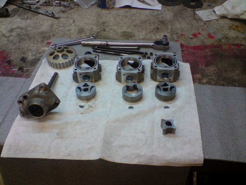
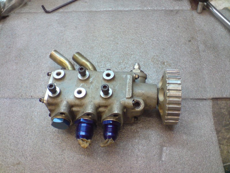
I stripped and rebuilt the Titan 3-Stage oil pump which will be the basis of my dry-sump system. The pump was a bit notchy. When I took it apart, there were some burs present on the outer-most diameter of the pump rotors. I de-burred them and re-built the pump. When it was back together it felt much better. I spoke to Lee who advised it should be fine so long as the Annulus' were not burred. So, job should be good.
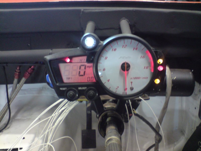
I powered up the R6 clocks to check I had the right wiring diagram for them. There is a nice out-of-focus photo of them to show what they are like with the back lighting on.
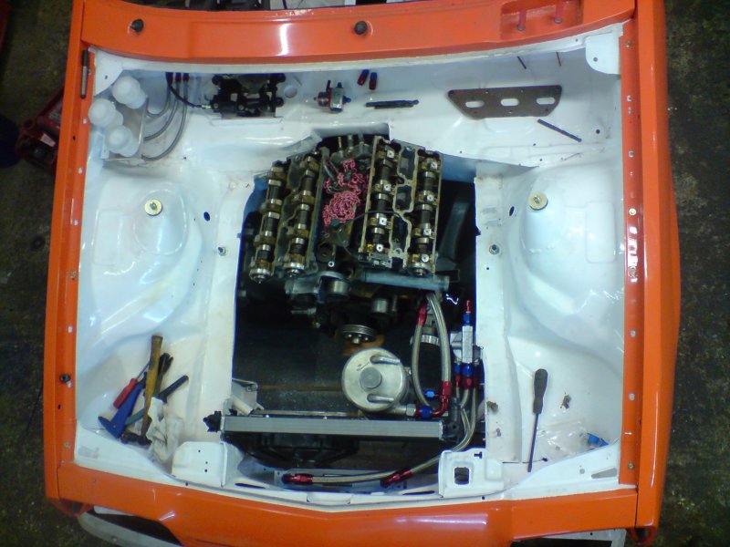
I have also started the oil and fuel plumbing for the engine. The radiator is fitted in place, I just need to make some clip-mounts for the top of it. The Dry-Sump tank is positioned, but needs it's bracket welding in place. I'll weld the bracket in place when the engine is mounted with the gearbox, just to make sure! The rad fan and oil cooler are in there too, so things are starting to come together.
I decided that I should also do some head work to the V6. As I will be running the V6 on throttle bodies it will be very beneficial to do some work on the heads. They are designed for high torque and not so much aimed at ultimate power. In the manta, I can bias towards power as the torque from a tuned V6 is always going to be enough as it's not exactly a heavy car.
The standard head design creates a venturi effect as the air passes the injector pintle - this speeding up of gas flow helps cylinder fill at mid-range revs and helps enhances the fuel and air mixture to increase torque. Another advantage I will have is the fact that I am running "Pico" injectors which can run a higher injector pressure and thus atomise the fuel more thoroughly compared to the standard bosch injectors.
The Standard inlet is not bad, the casting quality is okay; Not amazing, but okay. There are some standard places where gain can be made, and there are also big bonus places to make really good flow improvements. The C25XE inlet port shape is not beneficial to power because of the venturi design I mentioned earlier. It needs to be changed, ideally it should be increased to a circular inlet tract. The flow area at the inlet is only just that of a single inlet valve, ideally we are looking for around xx% of the TOTAL inlet valve area. Sorry, I didn't actually take any photo's of this part of the porting, although if you are porting a V6 head you'll see from the photos later on that the inlet port shape is very different to standard!
Part one of porting includes starting to knife-edge the siamese split, there are two big shoulders to remove and the front of the siamese split is very blunt in places. Ideally you'd be looking to have as shallow a split angle as possible, and the as little frontal area to the split as possible.
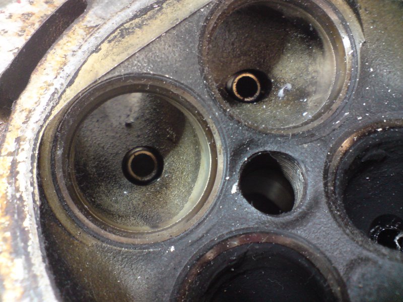
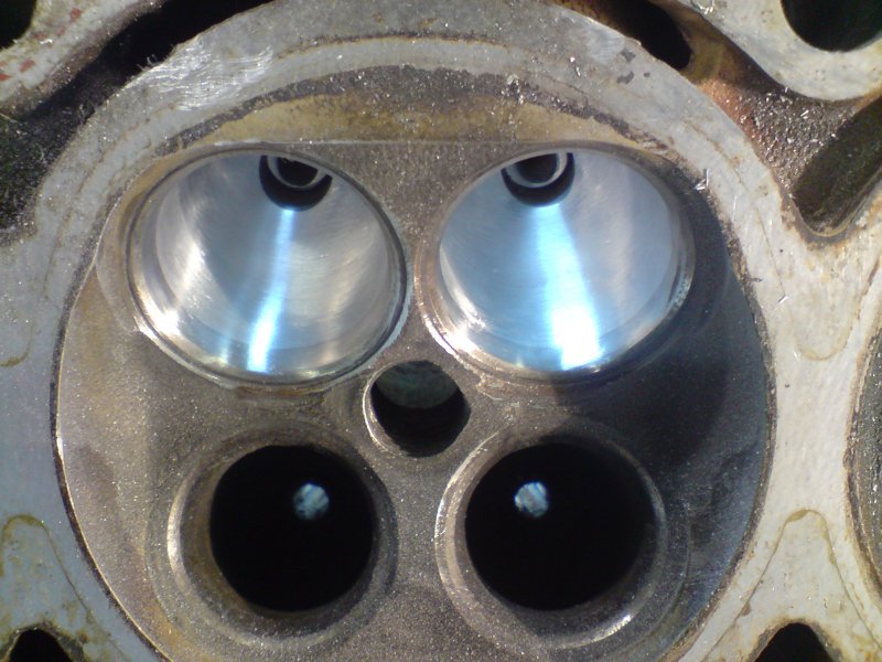
In the photo above, I've started knife edging the siamese split, and have opened out the right and left most port walls. The photo shows some of the typical places that flow gains can be made around the valve seats. Normally it's the valve seats where most of your flow gains will be made. With the V6 engine the inlet is so biased towards torque that you are likely to get good gains from increasing the port flow area; However, this can only be done if you are not running the C25XE plasting inlet manifold section.
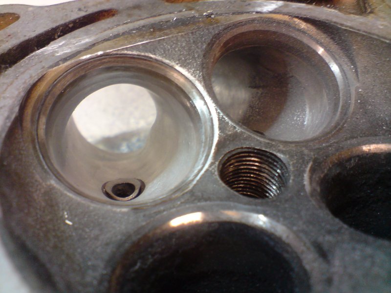
In the photo above, the short side radius defects can be shown. As the seat cutter enters the port, effectively smoothing the seat in part to the inlet port, it creates ridges on the short side radius. However, don't go taking too much material out of the short side radius because this will decrease the radius, and usually you will start to decrease flow ability because of increasing the turbulence. So, the rule is as little out of the port floor and short side radius as possible, but of course getting rid of the short side radius defects. Generally I just use some emery cloth along my finger and a few minutes with that is all it takes to correct the short side radius.
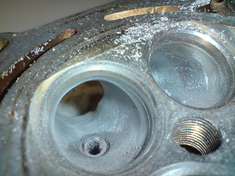
The long side radius has the highest gas flow speed, and so it is more critical than the short side radius to get gains from. In the photo above you can see something that exists in all hemi-chamber heads (or at least all I've seen), and that's the void right before the valve seat which continues to just after the valve guide. The flash has highlighted (or shadowed) it well so that we can see it. The long side radius needs working to that this is a smooth radius into the port from the port mouth to the valve seat opening. This means removing quite a lot of material from the port roof right by the valve guide.
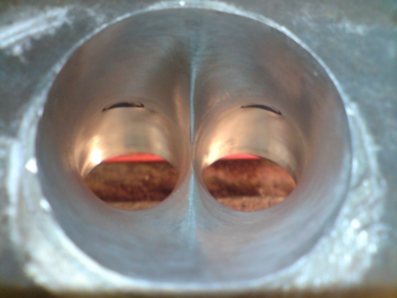
The inlet tract has been worked to smooth out the void on the long side radius and the short side radius is also blended. Actually, two things: (1) I took a bit too much out of the short side radius as I used a spiral band on a die-grinder to smooth it out rather than my normal emery cloth and finger method, and (2) I haven't really taken enough out of the port roof, there is still a slight dip.
The point is though, this is not an ultimate race head. If it was, I would have a bit more work to do. This level of porting is going to get the majority of ultimate flow through the head, and it means that I won't have to spend forever porting the heads, and I won't risk breaking through to a waterway and having to right a head off.
It's important to know what work is worth doing and what is just superficial pub talk. The finish I got I'm really pleased with considering how long it's taken me to port the head which is probably only a couple of hours for this inlet port. Copying over to the rest of the inlets should not take too long at all.
I used to use a drill for my porting work. All the heads I've done before have been done with a drill and a Flame shaped carbide burr, spiral bands and that's about it. However, today I used a die grinder and it's much quicker work. The burr is a lot quicker with a die grinder, you can really shift some material when you need to, it was particularly quick at doing the port roof.
Finally, as can be seen with the guides, I've ported straight across the top. The guides are actually in really good nick, so I will just be deburring the guides and leaving them alone rather than replacing them with Trojan or Bronze ones. My £50 engine is not looking too bad at all!